
By request I made a board that holds 8 channel temp controller. In this solution the sensors had be digital for high accuracy in a noisy environment, but there are also analog inputs that enables the module to be used as a generic 8ch PID controller.
Structure
 Each channel can select input source, ether digital SPI or analog input (12bit resolution). Each channel has it’s own PID and control settings.
The controller can be configured to work in many different ways.
The unit is powered by a 5 to 24v and can send status and settings trough an RS232 port.
Each channel can select input source, ether digital SPI or analog input (12bit resolution). Each channel has it’s own PID and control settings.
The controller can be configured to work in many different ways.
The unit is powered by a 5 to 24v and can send status and settings trough an RS232 port.
Temp Sensor
I used a small 5-pin SOT23 temp IC, LM95071 SPI/MICROWIRE 14-Bit Temperature Sensor. This gives me resolution of 0.03125°C between −40°C to +150°C.
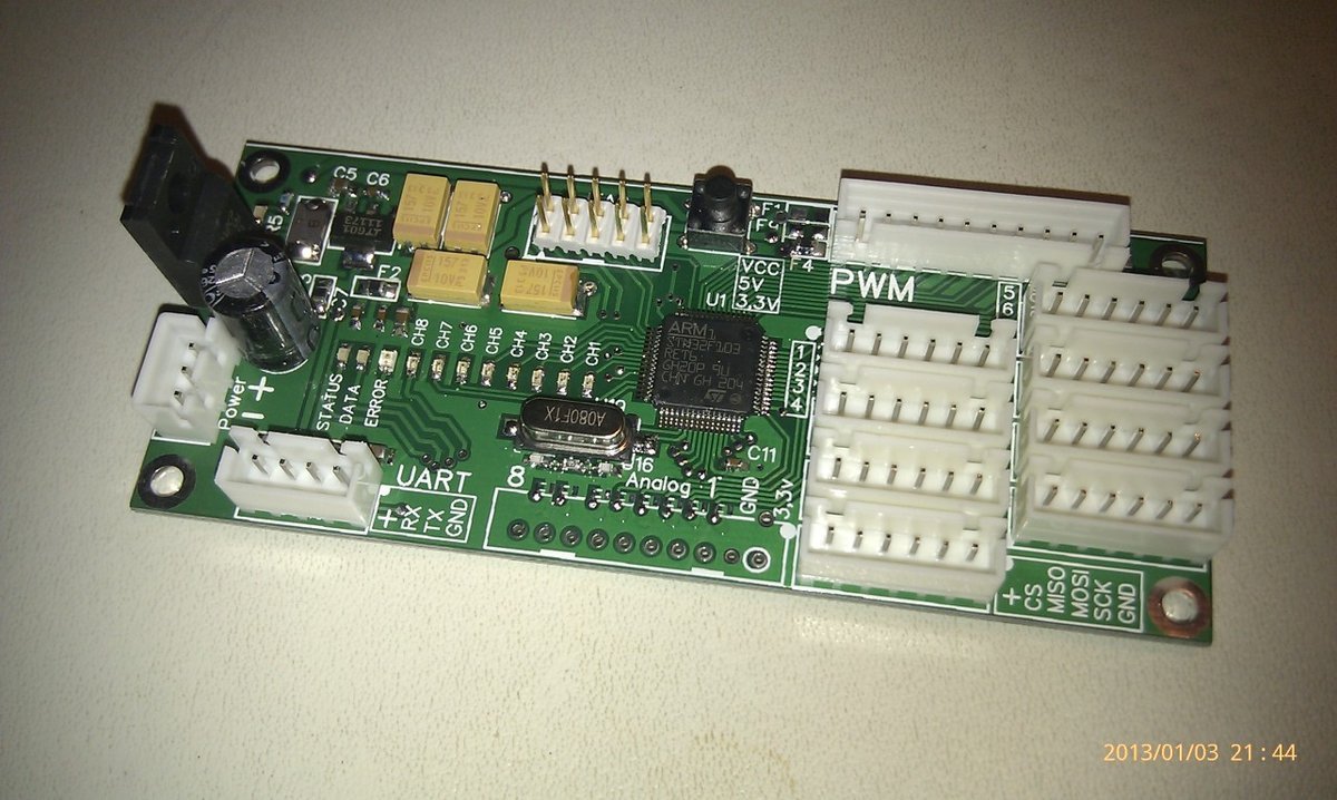
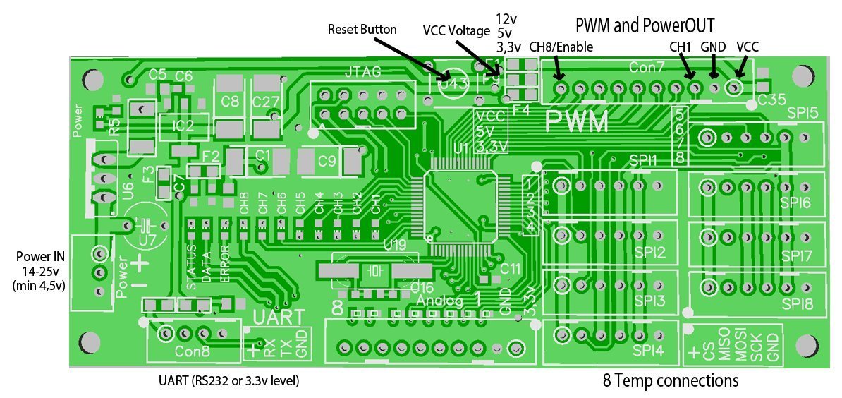
Board
Demo Video (sorry, there is only a Swedish version)
Settings
UART = 115200 RAW data to controller must start with $ and end with # !!!
Standard Functions
INF $INF# Show info data CLR $CLR# Clear (Resets) Settings, “Do not effect eeprom settings” SAV $BRN# Save settings data to EEprom (Burn current data into Eeprom) UPD $UPD# Update settings data from eeprom SWV $SFW# Show FW version
TempSensor port -> Temp Channel Select function
Select which TempSensor ( SPI port ) that selected TempChannel(PID regulator channel) should get it’s temperature from. TCS $TCS@1*3# Temp Channel Set, TempChannel 1 is set to use TempSensor on port 3
Enable/Disable functions
TCE $TCE*1# Temp controller Enable/Disable 0=Disable, 1=Enable (on enabled PID (I) is reset to Zero). All channels will be Enabled/Disabled. Only channels that is Enabled “CHE” will be activated on $TCE*1# CHE $CHE*1# Channel 1 Temp Control Enable (CH 1->8) on enabled PID (I) is reset to Zero. CHD $CHD*1# Channel 1 Temp Control Disable (CH 1->8) on enabled PID (I) is reset to Zero.
Main Setup functions
NOC $NOC*2# Number of active channels “in order” that should be used “0 to 8 -> CH0 to CH8” TUR $TUR*20# Temp and PID Update Rate in Hz, example = 20Hz DUD $DUD*2# Debug Update Divide, “Temp Update Rate”/DUD , in example 20Hz/2 = 10Hz. The debug data will be updated (sent) 10 times/sec SUR $SUR*1# SPI update Rate " SPI communications Freq" 0 = 140KHz 1 = 280KHz 2 = 500KHz 3 = 1MHz 4 = 2.25MHz 5 = 4.5MHz
SDS $SDS*2# Set Debug Status, example = debug is set to output channel 2 data Debug_Status = 0; No debug Debug_Status = 1; Channel 1 data Debug_Status = 2; Channel 2 data Debug_Status = 3; Channel 3 data Debug_Status = 4; Channel 4 data Debug_Status = 5; Channel 5 data Debug_Status = 6; Channel 6 data Debug_Status = 7; Channel 7 data Debug_Status = 8; Channel 8 data Debug_Status = 9; Send only every channels temp in visual form {Value in (int)(float * 10)} Debug_Status = 10; Send only every channels temp in visual form {Value in float} Debug_Status = 11; Send only temp from all channels in graph data Debug 1 to 8 data format (Temperature * 10: Temp_Ref * 10:** Temp_Error * 10**:** PID_Resualt / 10**:** P_Resualt / 10 : I_Resualt : D_Resualt : PWM**) all values are in Short HEX and separated by “:”, new data is separated with 0x0A = “/n”.** Channel Temp Settings SRT $SRT@1*51.6# Set Reference Temperature, example set CH1 ref temp to 51.6 deg
PID Settings
SPK $SPK@1*101.1# Set Pid K value for selected channel, example K = 101.1 on Channel 1 SPP $SPP@1*1.1# Set Pid P value for selected channel, example P = 1.1 on Channel 1 SPI $SPI@1*0.1# Set Pid I value for selected channel, example I = 0.1 on Channel 1 SPD $SPD@3*10.5# Set Pid D value for selected channel, example I = 10.5 on Channel 3
Channel Power Settings
SMP $SMP@1*100# Set Max Power “PWM Max Duty” 0-100% example, CH1 set to 100% as max power level SLP $SMP@1*0# Set Min Power “PWM Min Duty” 0-100% example, CH1 set to 0% as max power level
Power Invert function, For example active cooling equipment
CIE $CIE*1# Enable Power Inverted function on Channel 1 (0% power inverts to 100% power) CID $CID*1# Disable Power Inverted function on Channel 1
Example Channel1 Settings
// Set Reference Temp SRT@1*55.5 //// Set CH 1 K value SPK@1*1 //// Set CH 1 P value SPP@1*400.5 //// Set CH 1 I value SPI@1*0.5 //// Set CH 1 D value SPD@1*100.5 //// Set CH 1 Set Max Power SMP@1*50 //// Set CH 1 Set Min Power SLP@1*0 //// Set TempChannel1 to SensorPort 1 TCS@1*1
Example Main Settings
// Temp/PID Update Rate in Hz TUR*4 //// SPI update Rate , 0 = 140KHz SUR*0 //// Set Debug Status = No Debug SDS*0 //// Debug Update Divide DUD*2 //// Number of Channels that is active NOC*2